Main menu
Air Coil Design Engineering Notes
Air Dux™ Tele-Hints Sheet #8
Calculation Of Inductance

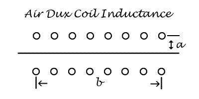
L = (a2N2) ÷ (9a + 10b)
Where N = Total Turns
a = radius length in inches
b = winding length in inches
Turns may be space wound or close wound.
The INDUCTANCE of coils with air cores is:
- Proportional to the square of the number of turns if the length and diameter of winding are kept constant as the number of turns are altered.
- Proportional to the size (length or shape) of coils having same shape (b/a) and same number of turns.
Thus two coils; one twice as big as the other with same number of turns has twice the inductance of the smaller.
The Q of a coil
Q = 2πfL ÷ R
Where f is frequency in Hertz and R is the Resistance of the coil.
The Q of a coil is dependent on a number of relative factors such as physical size, wire diameter, form factor, etc.
To obtain highest Q:
- Choose a size of coil where the length is moderately greater than the diameter;
- then choose wire size so that wire diameter occupies 0.5 to 0.75 of spacing between the turns.
- The LARGER the physical size of the coil, the HIGHER the Q will be- the fewer the number of turns required to obtain a given inductance- the larger will be the optimum wire diameter.
Mutual Inductance
The coefficient of coupling (K) between two coils:
K = M ÷ √L1, L2
Where M is mutual inductance L1 is inductance of first coil, L2 is inductance of second coil.
M, L1, and L2 can be in any units as long as they are the same in henries, micro-henries, etc.
Under conditions of resonance, the load, antenna, dummy, etc. couple resistance into the tank circuit in the amount:
(2πfM)2 ÷ R
where f is frequency in Hertz and R is the Resistance of the LOAD. Hence the LOADED Q of your tank circuit can be determined by knowing M if you know K.
- K varies from 0.35 to 0.37 if the coupling link is in the center of the tank but of the same diameter.
- When the link is over one end, the K is approximately 0.3.
- When the link is of the same diameter as coil but spaced slightly off the end, the K is approximately 0.2
- There is little reduction in K if the link in the center is wound over the tank coil on a large diameter form.
- When the link is of smaller diameter, K decreases in proportion to the reduction in diameter.
TANK COIL OVERHEATING
If the tank coil is overheating it may not need larger diameter wire- excessive circulating current in the tank may be the cause. If this is the case your final is POORLY designed and only a SMALL PORTION of your power is ending up at the antenna. Now, we could suggest using a very large conductor, but this would not SOLVE the problem. This large circulating current is passing through your switches and capacitor which is not good and eventual failure is probable.
Here are some points to keep in mind:
- Tank (pi network) circuit inductance is inversely proportional to EFFECTIVE Q of circuit, other things (load V, power output and frequency being equal.
QEFFECTIVE = ωL ÷ (RCOIL + Rcoupled from load).
The EFFECTIVE Q is the ratio of the coil reactance (ωL) to the SUM of the resistance inherent in the coil and resistance coupled into the tank circuit by the load.
- A high effective Q corresponds to a low L/C ratio with a resultant large circulating current, which, flowing through the resitance inherent in the coil causes heating. Conversely a lower effective Q corresponds to a high L/C ratio and a lower circulating current.
WIRE SIZE AND CAPACITOR SPACING VERSUS WATTS
Capacitor spacing based on representative voltages of input capacitor of a pi network or tank capacitor in a parallel tuned tank.
| BAND MHz | POWER INPUT | WIRE SIZE | CAPACITOR SPACING |
|---|---|---|---|
| 3.5 | 1000 W | 10 | 0.25" |
| 7.0 | 1000 W | 8 | 0.25" |
| 14.0 | 1000 W | 8 or 1/4" tube | 0.25" |
| 28.0 | 1000 W | 8 or 1/4" tube | 0.25" |
| 3.5 | 500 W | 14 | 0.08" |
| 7.0 | 500 W | 12 | 0.08" |
| 14.0 | 500 W | 12 | 0.08" |
| 28.0 | 500 W | 8 or 1/4" tube | 0.05" |
| 3.5 | 150 W | 18 | 0.03" |
| 7.0 | 150 W | 14 | 0.03" |
| 14.0 | 150 W | 14 | 0.03" |
| 28.0 | 150 W | 12 | 0.03" |
| 3.5 | 75 W | 18 | 0.02" |
| 7.0 | 75 W | 18 | 0.02" |
| 14.0 | 75 W | 18 | 0.02" |
| 28.0 | 75 W | 14 | 0.02" |
The output capacitor of pi network need not be more than 0.015" for a 50 ohms load at 1000 W input. For lower powers, receiving capacitors may be used in most cases.